Hi, my name is
Peter Ziegler.
I love to build things.
I'm a Mechanical Engineering student at UGA, and I want to understand how things work all the way down, from the physics of a 6-DOF arm to the code that drives it. Robotics, automation, and the mechanics of the human body are where that curiosity lives. Most of what I build sits at the messy intersection of physics, code, and the real world.
01. About Me
The thing I keep chasing is the gap between an idea and a working version of it. I'm a Mechanical Engineering student at the University of Georgia, and what I enjoy most is taking a complex system and finding the math that describes it, whether that's the forces on someone's spine during a lift, the motion of a person's joints through a stride, or the kinematics of a robotic arm. I like that the modeling isn't the end of it. A model is only convincing once it survives contact with reality.
That's the part I care about: not letting any of it stay abstract. At some point the math has to run, or the part has to come off the water jet and weld up straight, and that step is where I do most of my learning. I'm just as interested in deriving the equations as I am in building the physical piece, and I like robotics specifically because it forces both at once. Outside of engineering I love powerlifting and volunteering at the Brooklyn Cemetery restoration project in Athens.

02. Where I've Worked
Undergraduate Research Assistant @ UGA Physical AI Lab
Jan 2026 — Present Current
- Collected 100 iterations of demonstration data via teleoperation
- then trained a robot arm via imitation learning to perform basic tasks without human intervention. Currently researching 8 VLA policies to improve the accuracy and precision of robot actions.
Automation Engineering Intern @ Southern Flow
May 2025 — Aug 2025
- Designed the mechanical and pneumatic systems for an glycerin fill station for pressure-gauge diaphragm seals, then tested a prototype projected to cut subcontracted labor and cost by 40%.
- Built and deployed a pilot Remote Telemetry Unit transmitting temperature and humidity data over MQTT, then documented the full fabrication, integration, and configuration so the design could be replicated across sites.
- Produced AutoCAD wiring diagrams mapping Allen-Bradley PLC I/O cards for four customer installations, translating field wiring into clear, standardized schematics.
- Configured an Advantech protocol gateway converting Modbus RTU (RS-485) to Modbus TCP, allowing legacy equipment to communicate with modern Ethernet-based control systems.
- MQTT
- Onshape
- Autocad-LT
- Node-Red
- Vt-SCADA
03. Some Things I've Built
Featured Project
Spinal Loading Model
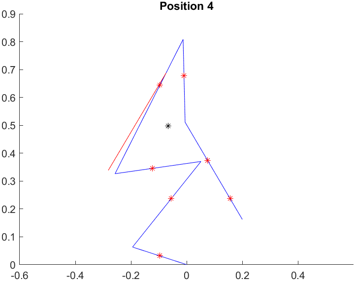
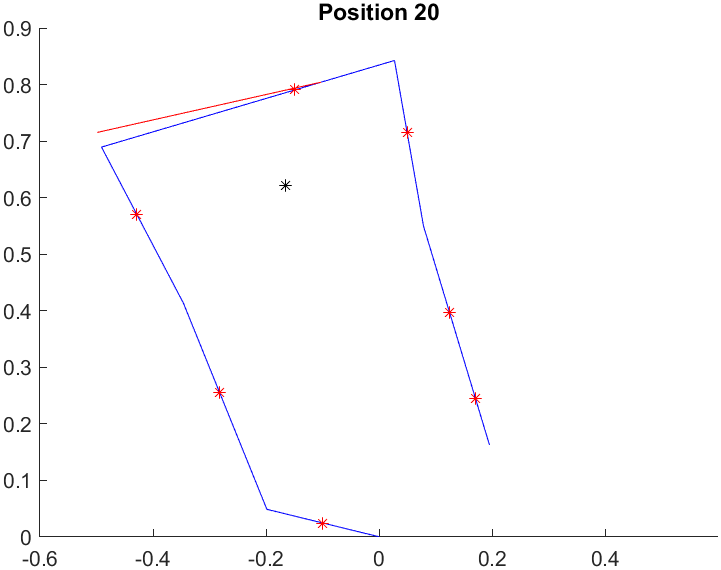
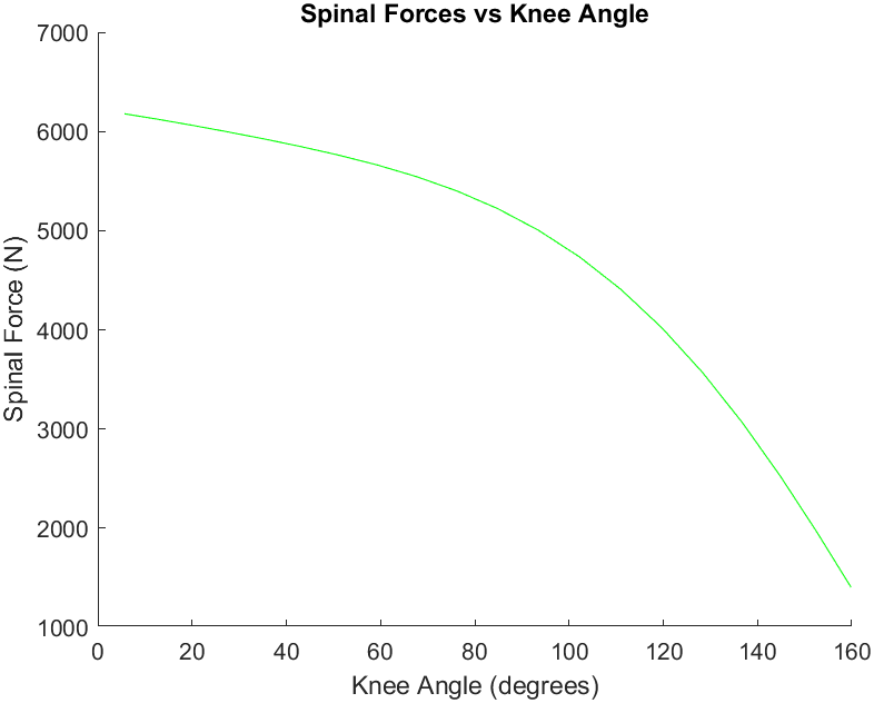
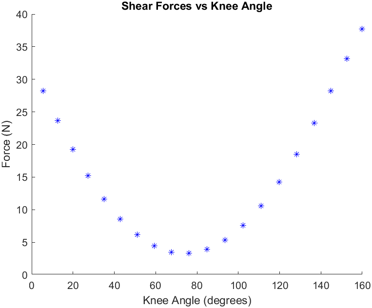
This project models a person lifting a 5 kg object and estimates the forces on their lower back across a range of postures, from a deep squat up to a nearly standing position. I was primarily responsible for building a 2D sagittal-plane model of the body as a six-link chain (foot, leg, thigh, trunk, upper arm, and forearm) using standard anthropometric data to set each segment's length and mass from the person's height and weight. For each posture, the code solves an inverse kinematics problem to find joint angles that place the hands at a target position. Additionally, this project assumes that the person is in quasi-static equilibrium which allows us to solve for the spinal force much easier. The output is a series of stick-figure plots plus summary graphs of muscle, shear, and compression forces versus knee angle, which together show why lifting form matters so much.
The hardest part was that the inverse kinematics problem is underdetermined. There are six joint angles but only two position equations, so most mathematical solutions come out biomechanically impossible, and MATLAB's fslove doesn't accept joint limits to rule them out. My teams workaround was to pick two anatomically reasonable end postures and linearly interpolate between them to generate 20 different initial guesses, steering the solver toward realistic poses without enforcing hard constraints. For the statics, we used 4×4 homogeneous transformation matrices to chain the body together so each segment's position and center of mass fell out of a single matrix multiplication, then built the equilibrium equations into a 3×3 linear system solved at every posture. To make sure the results held up, I added a sanity check on the hip-force decomposition into compression and shear, plus a base-of-support check on the body's center of mass to confirm each posture was actually stable.
Featured Project
Inverse Kinematics Solver
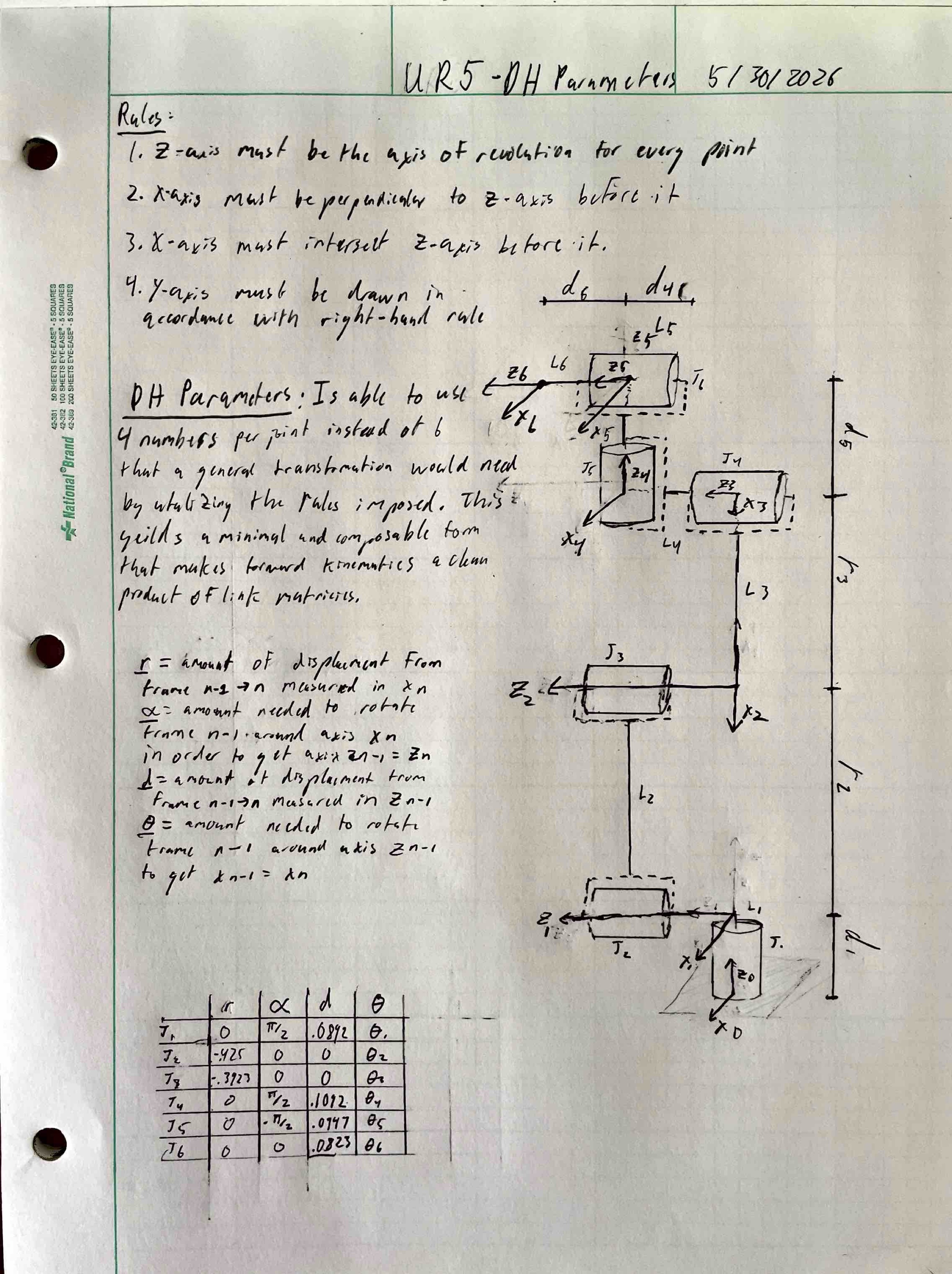
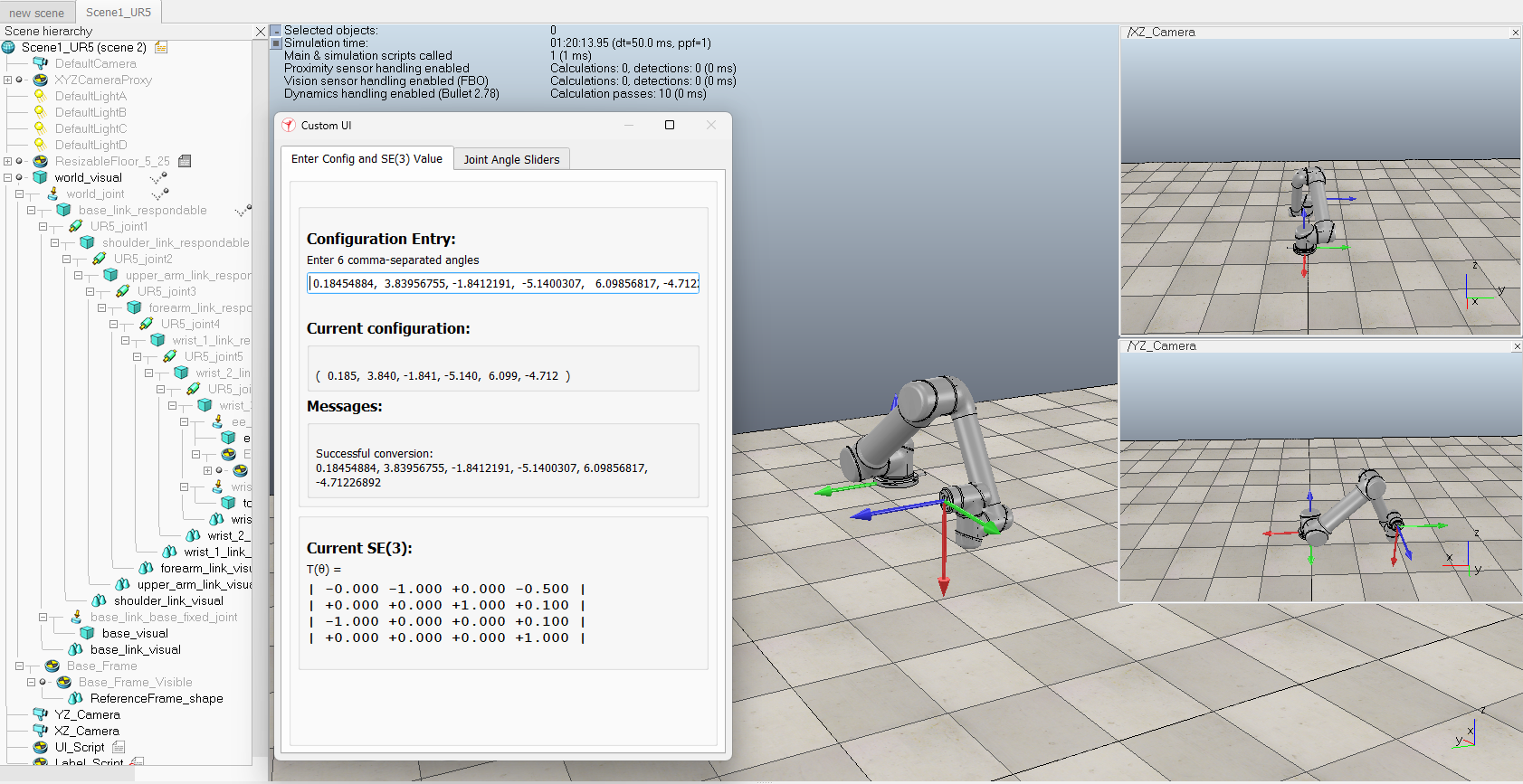
This project builds a numerical inverse kinematics solver for a 6-DOF UR5 robotic arm. Given a desired position and orientation for the end-effector, the solver finds the six joint angles that put the arm there. I described the robot's geometry using a standard Denavit-Hartenberg parameter table, then wrote a forward kinematics routine that chains the six joint transforms together to compute where the end-effector currently is for any set of joint angles. The IK solver is iterative: at each step it computes the 6D error between the current and target poses, builds the Jacobian matrix that relates joint velocities to end-effector velocities, and uses that relationship to figure out a small joint update that should reduce the error. Repeat until the error drops below a tolerance. To validate it, I plugged the output joint angles into a CoppeliaSim UR5 model and confirmed the simulated arm lands at the desired pose.
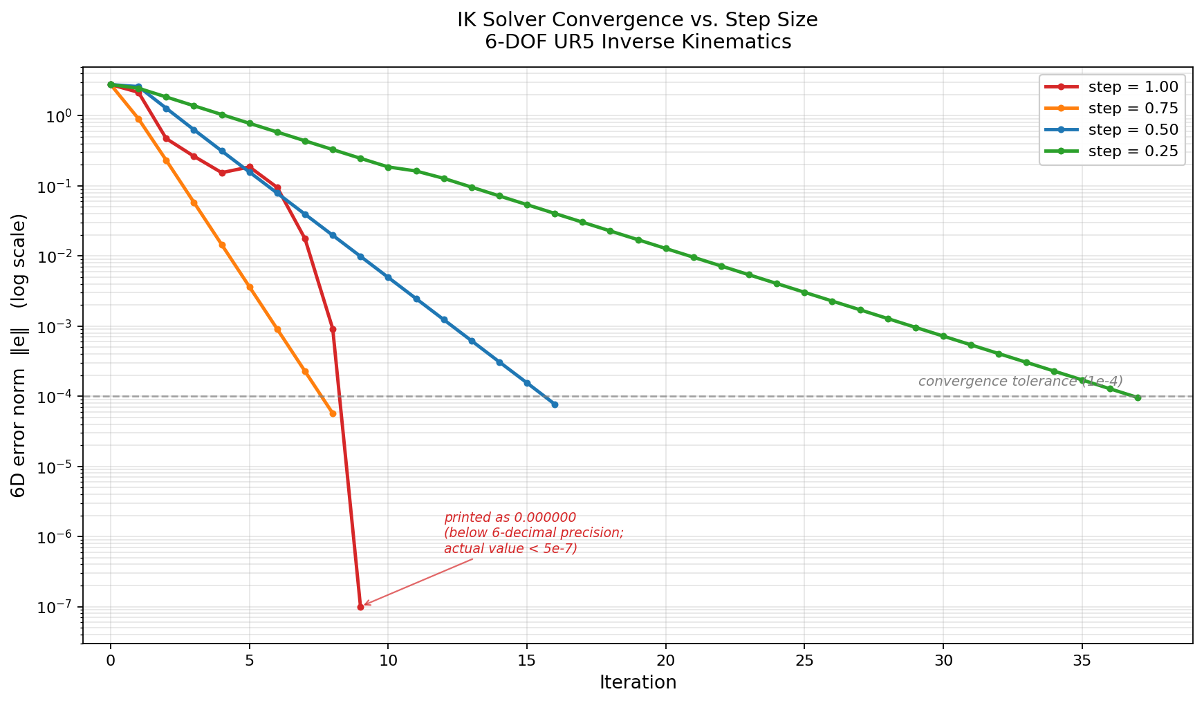
The two parts I found most interesting to work through were the orientation error and the step size. Position error is easy because you can subtract two 3D vectors, but orientation error needs more thought since you can't subtract two rotation matrices in a meaningful way. I computed the rotation that takes the current orientation to the target, then pulled the rotation angle out using the trace of that matrix and the rotation axis out of its off-diagonal entries. That gave me a single 3D vector representing "how much to rotate, and around what axis" that fits into the same error format as position. The step size turned out to be more intresting than I expected. The full Newton step is fast near the solution but can overshoot when you're far from it, so scaling each update by a fraction makes the solver more stable at the cost of more iterations. I tested several values and plotted the convergence behavior. The full step converged in 9 iterations but bounced around at one point along the way, while smaller steps were slower but near completely linear.
Featured Project
Disc Launcher
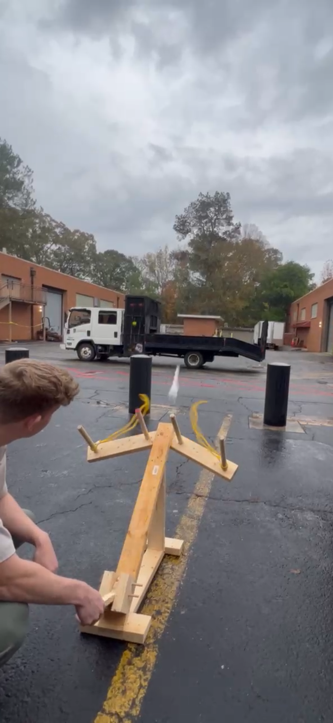
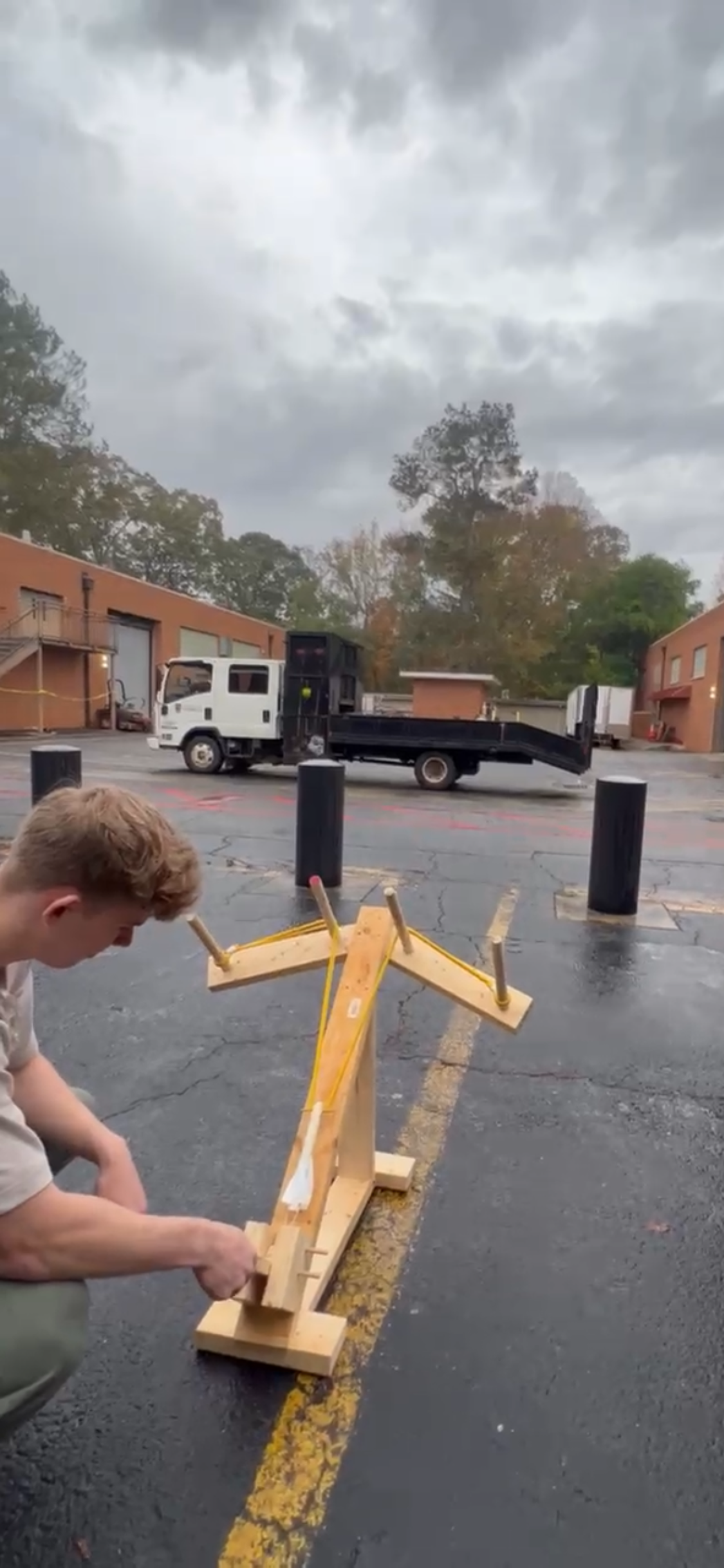
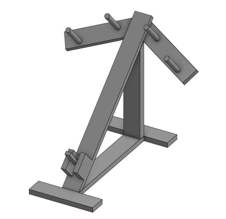
I worked with a team of five other student engineers to design and build a ballista-style launcher for a class project. My role focused on fabrication and performance testing, including building out the wooden frame and trigger mechanism and running the iteration cycles that pushed the launcher toward its final performance. The original goal was to launch a disc, but the disk was very light and flimsy, which meant that it was susceptible to very small changes in wind and would additionally deform substantially when shot from any powerful device. So the team and I made the call to embed the disc into a more aerodynamically stable dart-style projectile instead. That pivot ended up being the single biggest contributor to performance for the project and reframed how we approached the rest of the testing.
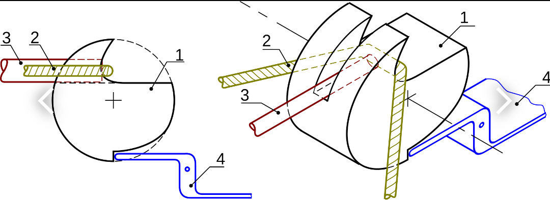
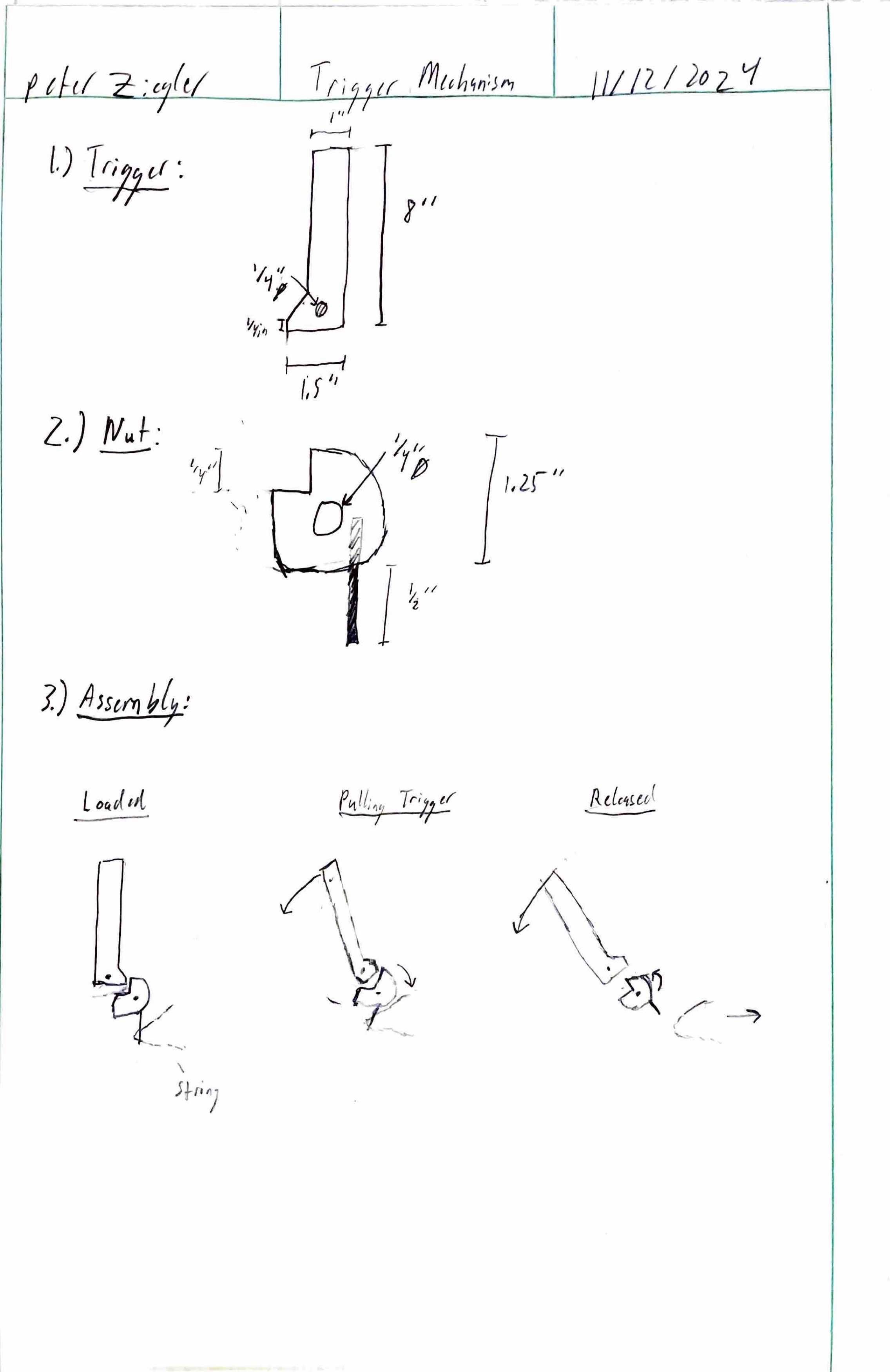
The trickiest piece was the trigger mechanism. We started with a medieval crossbow design as our reference, but translating that geometry into something that actually held up under our tension loads took several iterations. Early versions snapped under load, the string holder kept bending or slipping out of place, and getting the two contact pieces to mate cleanly enough for a consistent release was challenging. Each failure mode forced us to rethink either the material, the geometry, or the fit between the parts. Once the trigger finally released cleanly and predictably, our test data actually became relevant, since we could tell whether a distance change came from a design tweak or from a bad release. From there I ran iterative testing on dart geometry and launch angle, adjusting one variable at a time across multiple test sessions until we landed on a combination that pushed launch distance up by roughly 30% over our baseline.
Featured Project
Gait Analysis Model
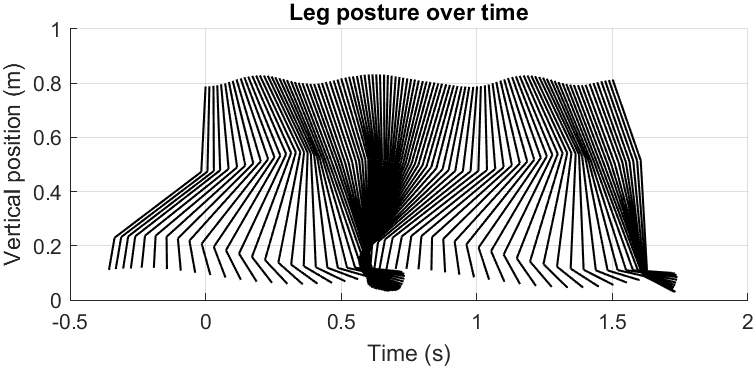
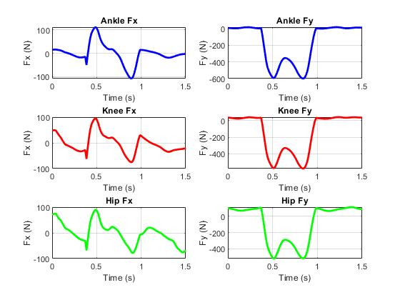
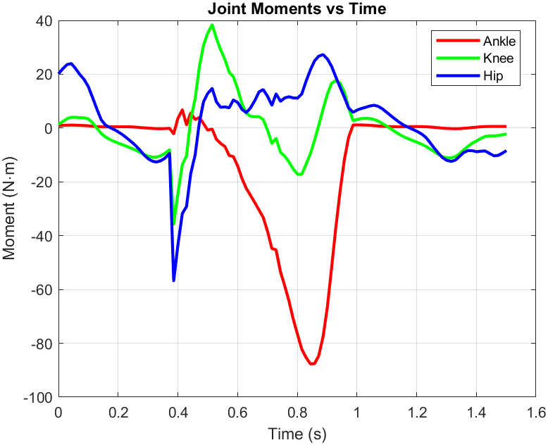
This project performs an inverse dynamics analysis on a person's leg during gait, using marker motion capture data and ground reaction force measurements to calculate the internal forces and moments at the ankle, knee, and hip joints over time. I built a 2D model of the foot, leg, and thigh using standard anthropometric data to set each segment's length, mass, and moment of inertia from the subject's body weight. For each frame, the script tracks segment angles and center-of-mass positions from the marker data, numerically differentiates to get linear and angular velocities and accelerations, then works up the chain from foot to hip applying Newton-Euler equations at each joint. The output is a plot of joint moments versus time along with x and y intersegmental forces at the ankle, knee, and hip, which together describe the internal loading the body produces during the recorded motion.
The biggest challenge was that numerical differentiation amplifies noise dramatically, so the raw marker data couldn't be differentiated twice without producing wild accelerations. I handled this by applying a moving-average filter to the raw marker positions and then again after each derivative step, which kept the velocity and acceleration signals in a workable state. I also wrote two helper functions for central difference differentiation, one for paired x and y signals and one for single angular signals, which kept the main script readable and made the velocity and acceleration calculations consistent across all three segments. The other tricky part was getting the moment equations right at each joint, since the sign of the moment arm depends on which direction the segment's unit vector points and which end of the segment the force is applied at. To build confidence in the results, I chained the analysis from the ground up, using each joint's solved reaction force as the input to the next segment so that any error would show up clearly in the following plots.
Other Noteworthy Projects
Object Avoiding Robot
Programmed an Arduino to receive sonar distance and direction signals, translate them into avoidance regions, and navigate around obstacles autonomously. Refined the detection algorithm to improve smoothness and accuracy, resulting in a 25% increase in operating speed.
Inverted Pendulum Table
Collaborated with another student and a faculty advisor to fabricate a rigid steel base for an inverted pendulum control system, where base stiffness directly affects the accuracy of the balancing control loop. Contributed to the geometric design of the structure and utilized MIG welding to join the assembly.
04. Technical Skills
CAD & Design
Programming & Software
Industrial Automation
Fabrication
05. Education
Bachelor of Science in Mechanical Engineering
GPA 3.51 / 4.0Certificate of Artificial Intelligence
University of Georgia College of Engineering
Relevant Coursework
- Biomechanics
- Thermodynamics
- Fluid Mechanics
- Strength of Materials
- Circuits
- Data Science 1
06. Get In Touch
Whether it's about an opportunity, a project, or just a chat about engineering and technology — I'd love to hear from you.